
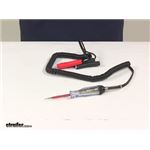
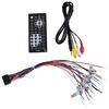
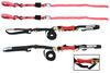
Computer Safe Logistic Probe
(7 reviews)
Price: $21.74
In Stock
Computer Safe Logistic Probe
Item # PTW2991
Retail:$37.63
Our Price: $21.74
You Save: 42%
In Stock


- All Info
- Reviews (7)
- Q & A (0)
- Videos (2)
- Photos
Performance Tool Electrical Tools - PTW2991
- Testers
- Circuit Tester
- Performance Tool
Features:
- Quickly tests high and low voltages on all vehicle circuits, including computerized engine and body controls
- Tests power and ground voltages
- Bright red and green LEDs interpret voltage signals such as ground, power and frequency
- Computer safe, drawing less than 7 milliamps
- Works on 6, 12 and 24 volt systems
- Recoil lead wire able to reach 10 feet
- Heavy gauge color coded battery clips
W2991 Performance Tool Computer Safe Logistic Probe
W2991 Computer Safe Logistic Probe
Installation Details
California residents: click here


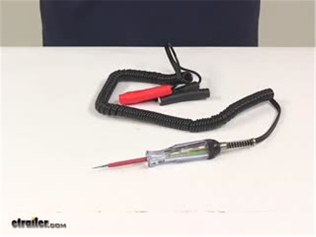
Video of Computer Safe Logistic Probe

Videos are provided as a guide only. Refer to manufacturer installation instructions and specs for complete information.


Video Transcript for Performance Tool Wiring - Tools for Wiring - PTW2991 Review
Today we're going to be taking a look at the performance tool computer safe logistic probe. It's going to feature a computer safe design drawing less then 7 mil amps. It will test high and low voltages on all vehicle circuits including computerized engine and body controls. It's going to feature a bright red and green LED. It's going to interpret voltage signals such as ground, power, and frequency. This system is designed to work on 6, 12, and 24 volt systems.
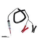
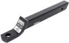
The test probe, that's this portion right here, that's going to measure pretty close to 3 and 3/16 of an inch, right around that area, 3 and 1/8. It's also going to come with your heavy gauge color coded battery clips. A really nice design, easy grip design on those. When the coiled cable or cord is fully stretched out it's going to be able to reach up to 10 feet. When you're ready to use or connect the probe what you'll need to do is you'll need to connect the probe clips to the vehicle's battery. The red clip, again, it's color coded so that's going to go to the positive terminal.
The black clip goes to the negative terminal. You'll need to turn the power on to the component or circuit being tested. Keep in mind the ignition may need to be in on or accessory position. In some cases the engine may need to be running. All you have to do is touch the components circuit wire with the probe's tip.
The LED will glow red if positive source is probed, or green if a negative source is probed. That tip right here, it's going to measure about 3 and 3/16 of an inch long and it's insulated. If the LED does not glow at all the probe may not be making contact with the wire. The wire or the component maybe faulty. Power may not be reaching the circuit or the circuit may not be properly grounded. That's going to do it for today's look at the performance tool computer safe logistic probe.
Customer Satisfaction Score:
93% were satisfied with this product
7% of customers were not satisfied
- Wrong item was ordered
Customer Reviews
Computer Safe Logistic Probe - PTW2991
Average Customer Rating: 5.0 out of 5 stars (7 Customer Reviews)
by: Nick06/11/2022
Exactly what I needed, much better than an old typical test light.
by: John B06/18/2017
Excellent electrical tester
by: David 09/10/2022
by: Michael 06/27/2023
by: Alan 04/08/2021
by: Richard 01/21/2022
by: John 05/12/2023
7
7
See what our Experts say about this Performance Tool Electrical Tools
- Lights Not Working After Installing Roadmaster Diode Wiring KitFirst, lets look at what is going on with the motor home. If it has a trailer connector on it you will want to test it using a circuit tester such as # PTW2991. If some of the circuits are not working then you know that the issue is on the motor home side. If they all check out fine then the issue is likely in either the kit used or the motorhome Using this will help you check for shorts in your current wiring.
view full answer... - No Plate or Running Lights but Brake and Turn Signal Work on New LED lights I recommend using a Probe Circuit Tester # PTW2991 to test the entire circuit. This type of tester will help you to identify both power and ground connections and that they are properly working. I have also included a link below that will help you to identify different wiring connections and where to check. I would begin by checking the power at the 4-way connection. Be sure to check it on both sides of the connector as there may have been a break inside the connector. From there you...
view full answer... - Trailer Light Wiring Diagram for 7-Way on a 2019 Chevy Silverado 2500According to my research the following wires for the 7-Way on your 2019 Chevy Silverado 2500 should carry the following functions: Green OR White/Green - Reverse White - Ground Blue - Brake Controller Green OR Green/Purple - Right Turn/Stop Red/Black OR Red/Green - 12V Power Brown OR Gray/Brown - Running Lights Yellow OR Yellow/Gray - Left Turn/Stop The reverse light function green wire should be slightly larger than the green wire for the right turn/stop function (if you have the 2 green...
view full answer... - Troubleshooting Trailer Loading Lights Connected to 2015 Dodge RamFrom your description it appears you do not have continuity from the batteries 12v supply to the pin for lighting. This may be due to a fuse or absence of that pin connected on your Ram where it is/was on the Chevy. Please see the attached wiring diagrams for assistance in trouble shooting and start with ensuring the pin for lighting on trailer is hot on the vehicle side. When referencing the 7-Way RV Plug diagram that I have attached, make sure you are looking at the plug the way the...
view full answer...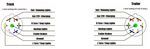
- Troubleshooting Trailer Turn/Stop Signals Not WorkingThere are a number of things to check when troubleshooting the left turn/stop and right turn/stop signals not working on your trailer. The first places to start are the connectors on both your tow vehicle and your trailer. Make sure that both are clean and free of any debris or corrosion. If you find something then clean it out and apply dielectric grease # 11755 to help keep the pins in good working order. If those look good then the next step is to determine if the signal is actually...
view full answer...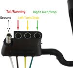

- How to Determine Where to Connect Tow Bar Wiring for 2019 Chevy Equinox PremierTo install the Universal Hy-Power Diode Wiring Kit # RM-154 on your 2019 Chevy Equinox Premier you will need to use a circuit tester like part # PTW2991 to determine what wiring colors for your tail lights carry which functions. Unfortunately we don't have a wiring diagram for your vehicle that I can pass along to you. Attached is an installation video on a 2018 Equinox that you can use as an example but I'd still test your wiring to make sure everything is connected to the proper circuit.
view full answer... - Furrion Backup Camera for 2014 Rockwood 5th Wheel and 3rd Brake Light Camera for 2012 Ram 2500I believe that you are correct about the wiring you found. You would want to test it with a circuit tester # PTW2991 though before installing the Furrion RV Observation Camera System # FOS05TASF as I am not sure what the wiring layout is for your 2014 Rockwood Signature Ultra Lite 8289WS 5th wheel. Attached are some review videos that you can check out.
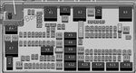
view full answer... - Locations for Left and Right Turn/Stop Trailer Fuses on a 2011 Ford F-450 Super DutyI took a look in the online version of the owner's manual for your 2011 Ford F-450 Super Duty and it looks like the right turn/stop is fuse location 13 while the left turn/stop is fuse location 14 in your passenger compartment fuse box. In the power distribution box (under the hood) the left turn/stop is location 74 while the right turn/stop is location 75. I recommend verifying this in your copy of the owner's manual. If these fuses look good but you still aren't getting a signal when...
view full answer...
- Will the Curt Echo Work with a 2006 Ford F-150 with the Factory Tow PackageIf the 7-Way on your 2006 Ford F-150 is from the factory then the 12V Power Pin in the 1 o'clock position should already be active. You can verify this by using a circuit tester like part # PTW2991 or a multimeter like part # PTW1714 to make sure there is constant power there. Some vehicle require that the key be in the on position for power to be sent to the 7-Way so if you initially don't have power try going that route. Let me know if you still don't have power and I can help you troubleshoot...
view full answer...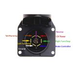
- Brake Controller For 2006 Toyota HighlanderI never go off the color that the wire is supposed to be. You will want to locate the brake light switch located under the dashboard. Once you have located the switch you will need to identify which wire gets power when the brake pedal is depressed. A Power Probe # PTW2991 will help you to identify the correct wire. The Installation instructions found on the Product Page # C24VV will help you identify the correct wiring required for the Brake Controller installation.
view full answer... - Trailer LED Tail Light Stopped Working on Right SideIt sounds like you are missing that 1 connection on the trailer tail light. Typically, a trailer tail light will have 2 or 3 wires. If it has 3 wires then there will be a ground wire (attached to the frame) a wire for brake lights and turn signal (these are the same wire) and a third wire for the running lights. You can use a circuit tester such as # PTW2991 to test the black wire to see which functions it is carrying. Have someone run through the lighting functions in the tow vehicle...
view full answer... - Trailer Wiring Harness for a 2014 Ford ExplorerCurt trailer wiring # C56172 is designed to fit a 2014 Ford Explorer that came with the factory tow package. If your Explorer does not have the factory tow package then the connectors for the harness will either not be present or they will not be functional. It sounds like your model does not have the factory tow package so you would need to use Hopkins harness # HM40285. It is also possible that the one connector you see and the one that is capped off are the connectors for the tow package...
view full answer...
- What are the Wire Functions for Transit LED Stop/Turn/Side Marker/Tail LightOn Transit LED Stop/Turn/Side Marker/Tail Light, # STL90RB, the white wire is ground, the red wire is for brake lights and turn signals, and the black wire is for running lights. It sounds like your trailer may have had separate turn signals from the brake lights. This would explain the 4 wires instead of 3. You will need to verify the functions of the trailer wiring using a circuit tester such as # PTW2991. Test each wire while the trailer is connected to the tow vehicle and have someone...
view full answer... - Adding Heavy Duty 4/7-Way Connector to a 2014 Jeep Cherokee Trailhawk with Light Duty Tow PackageThe heavy duty towing package on the 2014 Jeep Cherokee Trailhawk looks to be the same as # HM40975-11998. You could use this set up and what you would do is cut off the 4-Way and splice in the wires to the harness included with # HM40975-11998. On the harness the red wire is left turn signal and brake lights. White is ground. Green is right turn signal and brake lights. Brown is running lights. The functions that will not be used are the blue wire for electric brakes, black for 12 volt...
view full answer... - How to Ground a Trailer Light and Corrosion Prevention Yes, as long as you do not break continuity in doing so. I suggest you complete steps toward grounding trailer lights, verify proper grounding with meter or probe before addressing the area of concern. Once you have completed the process, check continuity one final time. I prefer to use a heat shrink ring terminal such as # DW05737-1 attached to grounding wire and a self tapping screw such as # FA1131822. The use of a self tapping screw will allow continuity of ground by way of drilled...
view full answer... - Trailer Brakes Will Not Lock Up with Primus IQ Brake Controller # TK90160 in 2007 Silverado 1500The fact that your trailer brakes will not lock up at 20-25 mph speed does not necessarily indicate a problem with the brake controller. The best way to isolate the problem is to apply a circuit tester to the wires leading into one of the trailer electric brake assemblies to read the voltage reaching the brake. You can use a voltage tester like # PT89ZR to read the voltage being delivered to the brake assembly. You should read +12 volts or very close to it at each brake when the controller...
view full answer...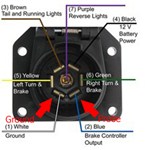
- Using Tail Light Convertor 118158 for a Third Brake Light and it Will Not Light UpMake sure that the tail light converter, # 118158, is properly grounded to a clean and corrosion free bare metal surface and do the same for the third brake light. Without a good proper ground the circuit cannot be completed. If this does not help then we need to do a little testing. First, disconnect the trailer and use a circuit tester such as # PTW2991 to test the vehicle side trailer connector just to make sure everything is working on that end. Next make sure the vehicle side and...
view full answer... - Troubleshooting New Brakes That are Weak After AdjustmentIf you have adjusted your Dexter Electric Trailer Brake Kit # 23-26-27 properly and you are getting no braking power with your override manual while your trailer is connected to your tow vehicle then I would start off by checking your 7-Way connectors for any corrosion or debris. If those look good the next step would be to determine if the brake controller signal is actually getting to the trailer or not. Using a circuit tester like part # PTW2991 test the pin in the 5 o'clock position...
view full answer...
- Tow Bar Wiring Causes Lights Not to Work on 1992 Elite Motorhome and 1997 Jeep Grand CherokeeYou are just going to need the proper wiring kit. It sounds like there are a combination of problems that are leading to the failures. There could be short and ground issues causing the lights not to work and the converter to blow. First, lets look at what is going on with the motor home. If it has a trailer connector on it you will want to test it using a circuit tester such as # PTW2991. I have included a link to a help article that explains how to test it. If some of the circuits are...
view full answer...
- How Does the Hopkins Agility Trailer Brake Controller Install on a 2003 Western Alpine RVThe Hopkins Agility brake controller # HM47294 does come with a harness so that you can hardwire it into a vehicle. If your 2003 Western Alpine was built on the Ford F-53 chassis by any chance, there may be a plug in harness available that would make installation easy. If it is the F-53 chassis, there is a brake controller plug located behind the instrument cluster. It is difficult to get to though. Take a look at the picture showing where it is. You would use harness # HM47855 to plug...
view full answer...
- With Trailer Connected Truck Reverse Lights and Trailer Brake Lights Are Not WorkingIt sounds like you might have a few different issues going on here. First, we need to test the vehicle side 7-Way connector to make sure it is working properly. Use a circuit tester such as # PTW2991 to test the pins on the connector while someone sits in the truck and runs through the light functions. If something does not work then you will need to determine the problem. Check the trailer connector for corrosion inside and out. Corrosion can cause all sorts of issues, so can ground...
view full answer... - Finding the Brake Switch Wire to Install a Brake Controller on a 2014 Toyota HighlanderYou have to test the brake switch wires with a circuit tester such as # PTW2991 to determine the correct wire for a brake controller red wire. You want the wire that only has power when the brake pedal is pressed and not with the headlights or turn signals on. On a 2013 Highlander we installed a brake controller on, the brake switch wire was blue. I would start testing with the blue wire on the brake switch if applicable to your 2014.
view full answer... - Where to Tap Into Reverse Light Circuit to Install Trailer Connector Adapter with Backup AlarmTo wire in the reverse light wire on Curt 7-Way connector # C57102 for the back up alarm to work you will need to tap into a reverse light wire behind a reverse light on your 1999 Dodge Ram. If you do not wish to tap into the wire there then you can trace the harness to a more accessible location. Then use a circuit tester such as # PTW2991, to find the correct wire before tapping into it. Be sure that the white ground wire on the 7-Way is attached to the truck frame. Otherwise the harness...
view full answer... - Brake Controller Error Message with 2012 Dodge 2500 4x4 Towing 2002 4-Star Horse TrailerThe problem you describe of your brake controller displaying an error message when your tow vehicle lights are turned on suggests several possible causes. One potential cause is damage/corrosion in the trailer connector(s) that could be causing two separate circuits to be bridged. It can happen that corrosion in a connector can actually create an electrical connection between two adjacent circuits, in this case the brake circuit and the running light circuit. Another possibility is that...
view full answer...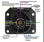
Do you have a question about this Electrical Tool?
Info for this part was:

Expert Research:
Jameson C

Video Edited:
Dustin K

Installed by:
Cole B

Installed by:
Brent H

Written by:
Mary K

Video by:
Zach D

Updated by:
Erin H
At etrailer.com we provide the best information available about the products we sell. We take the quality of our information seriously so that you can get the right part the first time. Let us know if anything is missing or if you have any questions.
Product Experts Available Now!
Call 1-800-940-8924
Thank you! Your comment has been submitted successfully. You should be able to view your question/comment here within a few days.
Error submitting comment. Please try again momentarily.